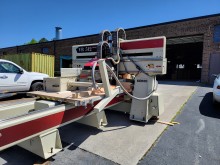
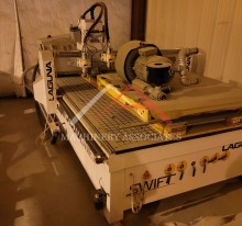
Hirzt Livra 1B Point To Point CNC - Great Condition
| MA ID: | RC3 - 6421 | ||||||||||||||||||||||||||||||||||||||||||
| Status: | Archived | ||||||||||||||||||||||||||||||||||||||||||
| Price: | $29,900.00 | ||||||||||||||||||||||||||||||||||||||||||
| Category: |
CNC Router (3-axis) |
||||||||||||||||||||||||||||||||||||||||||
| Manufacturer: | Giben | ||||||||||||||||||||||||||||||||||||||||||
| Model: | 1B | ||||||||||||||||||||||||||||||||||||||||||
| Year of Manufacture: | 2008 | ||||||||||||||||||||||||||||||||||||||||||
| Electric: | 480 Voltage 60 Cycle 3 Phase | ||||||||||||||||||||||||||||||||||||||||||
|
115.000,00 New o Set up time = 0. Machine operator can change panel sizes, panel processing requirements with zero time lost when making these changes. o Full flexibility – no limit in panel length or loss in productivity for longer panels. o Highly innovative boring process – providing immediate clean holes. Drilling is from the bottom of the panel, instead of the top, ensuring that shavings are completely & immediately removed from the holes. o The high quality side of the panel is not in contact with table- work surfaces, to ensure that the panel is not scratched. o Machineoperatorswillrequireminimaltraining. o Noadjustmentsrequired. o Simpleprogramming. The boring head carriage is designed with heat-treated steel that is built heavier and over-sized to provide more rigidity and precision for over a long period of time. Due to the large structure of the machine it is not necessary to anchor the machine to the ground. Technical Data
MACHINE CONFIGURATION Axis X - panel movement by clamps, travelling on rollers. Axis Y - boring head movement. AXIS “X” Movement is controlled in position “X” by clamps for panel feeding. With automatic step by step panel feeding and control of DANGER ZONE from CN. The motor is controlled by an encoder through a revolver. 60 mt /1’ Axis “Y” The control of the boring head movement is by motor with an encoder; with programmable speed and acceleration. Axis “Z” The control of the movement in the vertical boring and control of the height in horizontal boring. Movement is run by a program through a motor with an encoder. Axis “X1” HEAD CONFIGURATION Full Boring range of 800 mm with the possibility to process more. It is also possible, as an option, to process up to 1200 mm wide material.
|
|||||||||||||||||||||||||||||||||||||||||||
Please confirm all data before committing to a purchase.
*Subject to credit approval. Additional programs available.


